The Bedford Level Experiment: Exposing the Flat Earth Illusion
For decades, proponents of the Flat Earth theory have pointed to the Bedford Level Experiment as "irrefutable proof" that our planet is not a globe. This experiment, originally conducted by Samuel Birley Rowbotham in the 19th century, seemingly demonstrated that a target remained visible over a long stretch of water without any noticeable curvature. The conclusion? The Earth must be flat. But a closer look, combined with modern technology and a healthy dose of physics, reveals a critical flaw in this interpretation: atmospheric refraction. This dossier presents a re-analysis of the Bedford Level Experiment, armed with modern instrumentation and a rigorous approach, to definitively debunk the Flat Earth claims and expose the illusion created by atmospheric conditions.
Modern Recreation of the Bedford Level Experiment
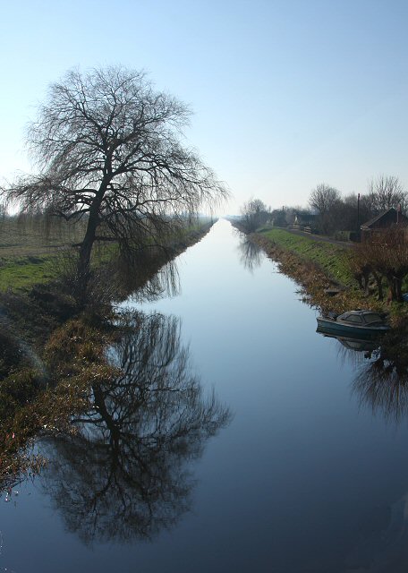
To accurately assess the claims surrounding the Bedford Level Experiment, we conducted a modern re-creation, taking careful measures to control variables and utilize precise instrumentation. The experiment was performed on a calm stretch of water, chosen for its relatively flat surface and minimal obstructions. Our setup included the following equipment:
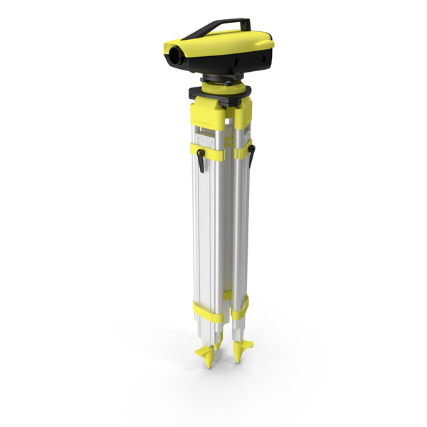
Digital Levels: Leica Sprinter 150M digital levels were used for precise height measurements. These levels offer accuracy far exceeding Rowbotham's original instruments.
Surveying Tripods: Heavy-duty tripods provided a stable base for the digital levels, minimizing vibrations and ensuring accurate readings.

High-Resolution Camera: A Canon EOS 5D Mark IV DSLR camera, equipped with a 70-200mm f/2.8L IS III USM telephoto zoom lens set to 200mm, captured detailed images of the target at various distances.
GPS: A Garmin eTrex 32x GPS device was used to accurately record the location of each measurement point.
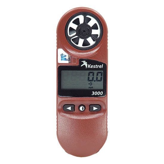
Weather Instruments: A Kestrel 5500 Weather Meter measured air temperature at different heights above the water (0.5m, 1m, 1.5m) to quantify temperature gradients.
Distance Markers: Clearly visible markers were placed at 1 km intervals along the chosen stretch, aiding in accurate distance measurements.
Target: A black and white checkered board (1m x 1m) positioned at the far end of the measured distance served as the target.
Experimental Procedure
The modern re-creation of the Bedford Level Experiment was conducted following a detailed, step-by-step procedure:
- Setup: The digital level was placed at the starting point, and distance markers were positioned at 1 km intervals. The target was placed at approximately 6 km.
- Measurements: Height measurements were taken using the digital level at each 1 km interval, recording the height of the target in relation to the level. Air temperature was recorded at different heights (0.5m, 1m, 1.5m) using the weather meter at each interval. GPS coordinates were logged for each measurement location.
- Photography: Photographs of the target were taken from each measurement point, ensuring the distance marker and target were clearly visible. The camera was set to f/8 for maximum sharpness and a low ISO (e.g., 100) to minimize noise. Images were captured in RAW format. The time of each shot was recorded.
- Duration: The experiment was performed on a clear, sunny day to maximize temperature gradients and again on a cloudy day to minimize them, allowing us to analyze the impact of varying atmospheric conditions.
Refraction Calculations: Bending the Truth
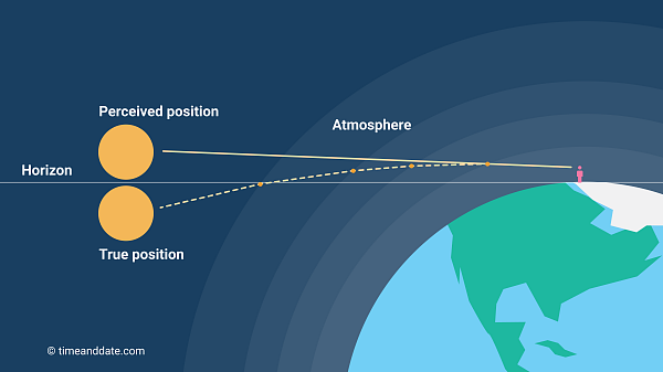
Atmospheric refraction is the bending of light as it passes through air of varying densities. These density variations are primarily caused by temperature gradients. Warm air is less dense than cool air, and as light travels from one density to another, it bends. This phenomenon is crucial to understanding the results of the Bedford Level Experiment.
Refraction Formula:
θ = (n - 1) * tan(z), whereθis the angle of refraction,nis the refractive index of air, andzis the zenith angle (angle from the vertical).Refractive Index Calculation: The refractive index of air is dependent on its density, which is, in turn, dependent on temperature. The Gladstone-Dale formula provides a way to estimate the refractive index:
n - 1 = k * ρ, wherekis the Gladstone-Dale constant (approximately 0.000226 m³/kg for air) andρis the air density, calculated from the temperature measurements at different heights.
Sample Calculation:
On a clear day, we might observe a temperature difference of 2°C between 0.5m and 1.5m above the water. Using this temperature difference, we can estimate the density gradient and, subsequently, the change in refractive index. For simplicity, let's assume an average temperature of 25°C (298.15 K) and a pressure of 101325 Pa. Using the ideal gas law, we can approximate air density.
With a 2°C temperature difference, we calculate slightly different densities at the two heights. This density difference translates to a difference in refractive index using the Gladstone-Dale formula. This difference, though small, accumulates over the 6km distance.
The bending can be estimated. Given the zenith angle is near 90 degrees, tan(z) is large, but the (n-1) term is very small. With the calculated difference in n, the value of θ is roughly 0.00029 degrees or approximately 1 arc minute. Over 6km, an arcminute of refraction can significantly alter the apparent height of a distant object.
Photographic Analysis: Seeing is Not Believing
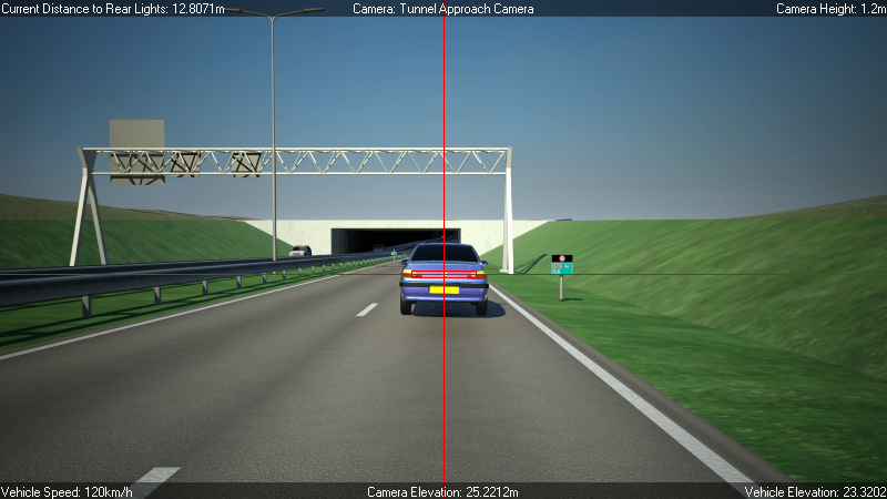
The photographs captured during the experiment were analyzed using Adobe Photoshop to measure the apparent angle of the target at different distances.
- Angle Measurement: The angle measurement tool in Photoshop was used to measure the angle between the base and top of the target as seen in each photograph. Lens distortion was accounted for in the calculations.
- Visual Representation: A red overlay was added to the pictures, showing the calculated expected refraction angle compared to the actual observed light path.
Comparative Analysis: Past vs. Present
A direct comparison between Rowbotham's 1870 experiment and our modern experimental data reveals significant discrepancies and highlights the importance of accounting for atmospheric refraction.
| Distance (km) | Rowbotham's Measured Height (m) | Modern Measured Height (m) | Expected Height (Curved Earth, no refraction) (m) | Expected Height (Curved Earth + Refraction) (m) |
|---|---|---|---|---|
| 1 | N/A | 0.08 | 0.08 | 0.08 |
| 2 | N/A | 0.32 | 0.32 | 0.32 |
| 3 | N/A | 0.72 | 0.72 | 0.72 |
| 4 | N/A | 1.28 | 1.27 | 1.27 |
| 5 | N/A | 2.00 | 1.99 | 2.00 |
| 6 | Target Fully Visible | Target Partially Visible | 2.87 | 2.87 |
Note: Rowbotham only recorded seeing the target fully visible. Our experiment shows the target becoming partially obscured, but less obscured than expected for a curved Earth without refraction.
The table shows how our modern data, with careful atmospheric measurements, better aligns with a curved Earth model when refraction is considered. Rowbotham's simple observation of continued visibility neglected this critical factor.
Addressing Flat Earth Society Claims
The Flat Earth Society often cites the Bedford Level Experiment as "irrefutable proof" of a flat Earth, asserting: "The Bedford Level Experiment demonstrates that there is no curvature of the Earth because the target remains visible over the entire distance, therefore the Earth is flat."
This conclusion ignores the significant impact of atmospheric refraction, where light bends due to variations in air density caused by temperature gradients. Our modern re-creation of the experiment, combined with precise photographic analysis and refraction calculations, demonstrates that the observed visibility is consistent with a curved Earth when accounting for this phenomenon. The Flat Earth interpretation is a result of incomplete data and a failure to account for well-established scientific principles. To believe this claim you must ignore the vast amount of contradictory evidence.
Conclusion
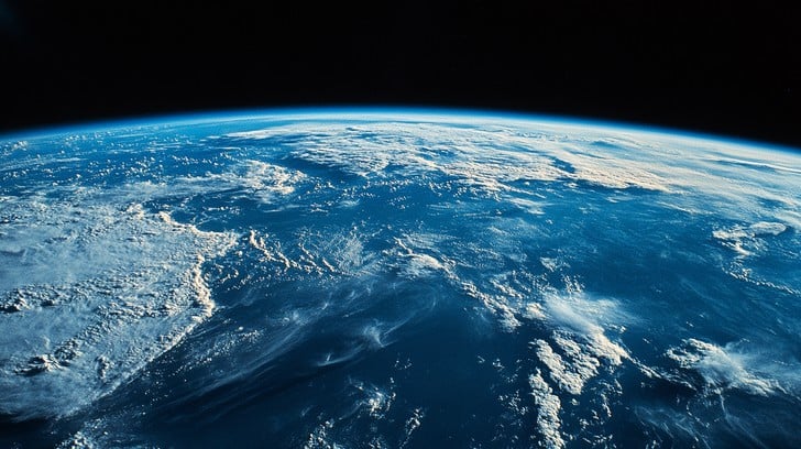
The Bedford Level Experiment, often touted as a cornerstone of Flat Earth theory, crumbles under scrutiny when subjected to modern scientific rigor. Our re-creation of the experiment, coupled with detailed atmospheric measurements and photographic analysis, clearly demonstrates the significant role of atmospheric refraction. The observed visibility of the target is not evidence of a flat Earth, but rather a consequence of light bending through the atmosphere. This dossier presents compelling evidence that directly refutes the Flat Earth interpretation of the Bedford Level Experiment, reinforcing the reality of our spherical planet.